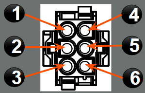
6 Pin Out From AC to Control Box

  • Terminal 1 BLUE Compressor
  • Terminal 2 BLACK High Fan
  • Terminal 3 YELLOW Medium Fan
    (or Heat Pump Rev Valve CCC/Analog)
  • Terminal 4 RED Low Fan
  • Terminal 5 WHITE Neutral
  • Terminal 6 GREEN/YELLOW Ground
    (Ground is sometimes GREY)

Thermostats

Captive Touch

Operating Instructions

System Initializing & Diagnostic Mode

LCD

LCD Operating Instructions

  • With the thermostat turned off, simultaneously press and release the “UP”, “DOWN” And “MODE” buttons (Do NOT need to hold).
  • Display shows the diagnostic command “00”. At this point you are in Diagnostic Mode.
  • Use “UP” & “DOWN” arrows to cycle through the commands.
  • Compressor, heat strip, furnace, fan, reversing valve outputs can be turned ON & OFF.
    • Caution – 120 second compressor delay is disabled
Command  Description Comment
00 All outputs OFF
01 Low Speed Fan ON
02 High Speed Fan ON
03 Compressor ON
04 Furnace Output ON
05 Reversing Valve ON Heat Pump unit Only
06 Heat Strip ON Heat Strip unit Only
07 LCD shows Room Temperature  Or E2 / E3
08 LCD shows Evaporator Coil Temperature  Or E5 if missing
09 LCD shows Outdoor Temperature (HP only) Or E4 if missing

Note: Control units that are not designed for the Heat Strip or Heat Pump options will not have those specific commands available in the Diagnostic Mode with the SZLCD thermostat. Commands 5 & 9 will only show on Heat Pump models and Command 6 will only show on Heat Strip models unless you have the CT thermostat.

ERROR CODES

  • E1 – Loss of communication 
    • Causes Relay Control Module to shut down
    • Always try system reset to establish communication
    • Possible issue with Communication Wire (short, cut, removed)
    • Can be caused by interference (RF)
  • E2 – Room Air Sensor Open/Out of range Circuit
    • No Heat or Cool operation
  • E3 – Room Air Sensor Short Circuit
    • No Heat or Cool operation
  • E4 – Outdoor Ambient Sensor Out of Range
    • No Heat Pump operation (specific to HP Models)
    • Verify Sensor is plugged in
    • Make sure the sensor is working by checking the Ohms
  • E5Freeze Sensor Out of Range/Sensor Open
    • Air Conditioner operation inhibited
    • Make sure Freeze Control is plugged in
    • Verify the sensor is working by checking the Ohms

Troubleshooting Tips

  • Check sensor temperatures measured by the CT/SZLCD.
    • Sensor temperatures are displayed in diagnostics.
    • Operations may be inhibited by sensor temperatures.
    • Check the Ohms value of outside ambient sensor for Heat Pump models
  • Use diagnostics mode to test compressor, heat pump, heat strip, furnace, & fan outputs.
    • There is no 120 sec. delay in the diagnostics mode.

Manufacturer Troubleshooting Guide

System Reset

    • Turn the ON/OFF switch to the “OFF” position (Bottom of T-stat).
    • Simultaneously press and hold the “MODE” & “ZONE” buttons and then turn the ON/OFF switch to the “ON” position. 
  • “FF” should appear on the display. At this point you can release “MODE” & “ZONE”
  • If “EE” appears when the buttons are released, perform the reset again. If “EE” keeps displaying, there is a communication problem issue in the system.
  • When a dip switch is turned on or off after initial configuration, a reset must be performed to allow the comfort control center to recognize the updated change. 
  • Any time a component is added or removed, it is best to perform a reset.

Troubleshooting

When EE is displayed on the T-Stat

  • Disconnect all communication cables to all units but the unit with the T-Stat (Zone 1) and do a reset.
  • If that zone works, and no EE is present, you know the comm cable and control board for that unit is working. 
  • Connect the next zone and reset. 
  • With each zone connected do a reset. 
  • When a zone is connected and the EE is displayed that zone has a problem with the cable or control board. 
  • When you find out where the problems lies (specific zone) you will need to determine if the cable or the control board is the issue using a test RJ-11 Cable. 
  • Remove the “installed” cable from the equation and use your test cable, do a reset, if the problem is still persistent then the board is defective. If the problem goes away you know the issue lies in the “installed” cable that was removed during testing with test cable. 


Manufacturer Troubleshooting Guide

Operating Instructions

Quick Reference

  • With the thermostat turned off (screen backlit), simultaneously press and release the “Program”, “Fan” and “F/C” buttons. 
  • Display shows “DIGN”, the zone and the diagnostic command.
  • Use up & down buttons to cycle through commands.
Diagnostic Command  Description Comment
00 All outputs OFF No Operation
01 Low Speed  Low Fan On
02 Medium Speed  Medium Fan On
03 High Speed  High Fan On
04 Reversing  Reversing Valve On
05 Compressor ON Compressor  Running
06 Heat Strip  Heat Strip On
07 Furnace Output On Furnace On
08 Load Shed Output On Compressor Off
09 LCD shows Indoor Temperature for the Remote Sensor E2 if missing, E3 if shorted
10 LCD shows Outdoor Temperature  E4 if missing
11 LCD shows Evaporator Coil Temperature  E5 if missing
12 LCD shows 120 VAC status ‘On’ or ‘– – ’ 
13 LCD shows Load Shed Status ‘On’ or ‘– – ’ 
14 LCD shows Stage DIP Switch Position ‘On’ or ‘– – ’ 
15 LCD shows Heat Strip DIP Switch Position ‘On’ or ‘– – ’ 
16 LCD shows Heat Pump DIP Switch Position ‘On’ or ‘– – ’ 
17 LCD shows Furnace DIP Switch Position ‘On’ or ‘– – ’ 
18 LCD shows Dehumidifier DIP Switch Position ‘On’ or ‘– – ’ 
19 LCD shows Gen Start DIP Switch Position ‘On’ or ‘– – ’ 
20 LCD shows Ext Stage DIP Switch Position ‘On’ or ‘– – ’ 

Tip: You can go through these commands one of two ways. You can either go through commands 1-20 in a specific zone (Zone 1-4), or you can go into a specific command (5 – for compressor for example) and while staying in that specific command, hit the ZONE button to check the same command on the next zone and so on.

ERROR CODES

  • E1 – Loss of communication 
      • Two power module DIP switches set as same zone.
      • Possibly a faulty communication cable.
      • 12 Volt DC not clean, try direct DC from battery.
      • Causes power module to shut down.
  • E2 – Room Air Sensor Open Circuit
      • Unlikely to occur; if no remote sensor, CCC2 wall thermostat built-in sensor is used.
      • Useful in diagnostic mode to test if remote sensor is installed on zone or open.
      • No heat or cool operation.
  • E3 – Room Air Sensor Short Circuit
      • Error shown if either remote sensor or CCC thermostat built-in sensor is shorted.
      • No heat or cool operation.
  • E4 – Outdoor Ambient Sensor Out of Range
      • No heat pump operation.
  • E5 – Freeze Sensor Out of Range
      • No AC operation. 
  • E6 – Open Circuit Humidity Sensor 
      • Dehumidify operation is inhibited (not used on current units).
  • E7 – 120 VAC not Detected
      • 120 second delay to allow for GEN START operation.
      • All 120 VAC relays switched off (furnace relay not affected).
      • Verify white neutral wire on control board has good connection to run capacitor and that capacitor is good.
  • E8 – Invalid Zone Configuration
      • Heat pump & heat strip selected on same zone. Not allowed on the CCC 2 system.
      • No heat or cool operation on zone.
  • E9 – Invalid Zone Configuration
      • Dehumidify along with Heat Pump or Heat Strip
      • No heat or cool operation on zone. 

Manufacturer Flat Rate Schedule

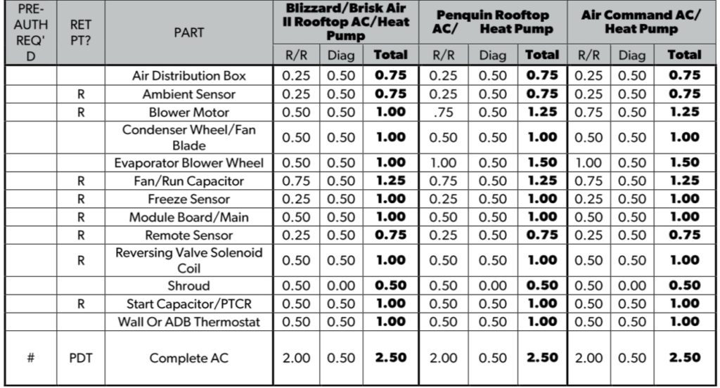
The diag time is sometimes stackable on the manufacturer warranty as a separate code paid by Dometic